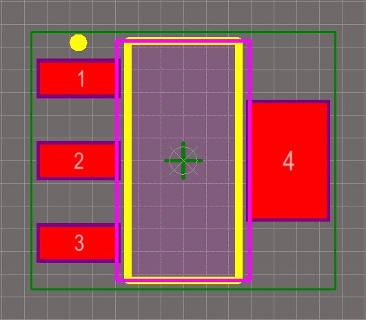

It is particularly sobering when someone new to designing PCBs learns that components aren’t simply included in the package like different fonts are included in Microsoft Word. Finally, a company large enough to have a CAD team will typically have a ‘best practices’ list for their components.

A high-density board will require the tightest possible footprint event if that means higher manufacturing costs and lower yield, while a low-density, low cost board will use giant footprints to allow for loose manufacturing requirements. There are many different eCAD packages that each have their own data format, layers, and requirements - and each project will have its own aesthetic and technical requirements. Component generation is a rich problem thanks to the wide variety of footprints needed for a particular component and the importance of having it done exactly to spec. This article will go through many of the options available today and some pros and cons of each. The hassle is not lost on anyone, and there are many different solutions that have been released over the past several years. Making footprints and schematic symbols has to be one of the most tedious stages of PCBA development.


 0 kommentar(er)
